|
|
|
|
Hardware Help
| ALFORD SLOT ANTENNA |
|
24
cms AERIALS |
|
INTRODUCTION The
Alford Slot antenna, which has been developed for l.3GHz by G3JVL, is an
easy means of obtaining an omni- directional radiation pattern with
horizontal polarization . The antenna has a gain which depends
principally upon its length and is typically 5 to 9 dBi . This is a
better performance than other simple omni-directional antennae commonly
used such as halos or whips. It is particularly suitable for a beacon or repeater antenna where an omni pattern is required with as high a gain as possible. In this application it is possible to stack two such antennae end to enc3 (as used at the beacon GB3IOW) and nearly double the gain. with higher path losses on 23cm compared to 2m and 70cm the extra gain makes it particularly useful as a mobile antenna. |
|
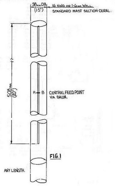
DESCRIPTION The antenna consists of a length of slotted tubing as shown in figure l. The width and length of the slot, the wall thickness and the diameter of tubing are all related and much experimental work has been done by G3JVL and G3YGF to evolve some working designs, details of which are given below. |
|
Tube Dimensions
Slot Width
Slot Length 31.8mm
OD, 20swg wall 4
mm 510
mm 35.8mm
OD, l.lmm wall 8
mm 510
mm 38.1mm
OD, l6swg wall ll
mm 510
mm
|
|
The
dimensions cover three common sizes of tubing available (copper, brass
and aluminum materials are all suitable). If they are not followed
exactly then some experimentation will be necessary for correct
operation. In any case, it is advisable to check the field distribution
in the slot as explained later. |
 |
 |
|
The
length of tube beyond the slot is completely uncritical and the same
tube could be used both as a mast and as an antenna! This includes the
length of tubing above the short, so that either a simple short across
the slot or a disc covering the top can be used, or the tube can be
extended upwards in a similar manner to the bottom. The
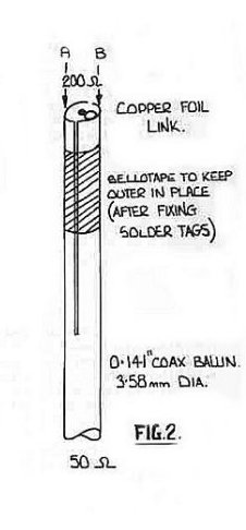
feed impedance of these antennae is approximately 200 ohms. A convenient
method of feeding from 50 ohm coax is to use a 4:1 balun which is
fabricated from semi-rigid coax, as shown in figure 2. It consists of a
piece of 0.141 inch (3.6mm) semi-rigid with two slots cut along opposite
sides of the outer. The two leaves formed by the coax outer form a twin
wire transmission line which; is a quarter wave long, and short
circuited at one end. This quarter wave resonator is excited by
connecting the coax inner conductor to the end of one of the leaves. The
two sides of the semi-rigid a and b are connected to the feed point of
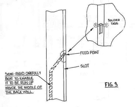
the slot (see fig:1 and 2). A convenient method of doing this is to
attach small solder tags to the cable so that small screws can then be
used to attach the balun assembly to the sides of the slot. The
cable should be bent round after leaving the feed point so that it sits
somewhere between the back wall and the center as it passes down the
tube. The exact arrangement is uncritical so long as the cable does not
come too close to the slot and upset its operation (apart from the feed
point of cours |
 |
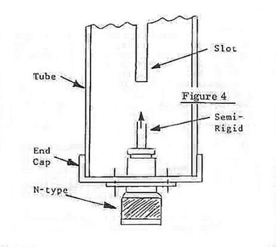
| It
is not necessary to connect the cable to the inside of the tube as it
passes out of the bottom. However, a convenient method of mounting is to
fit d shorting plate of some description across the bottom with an
N-type plug or socket in it. The antenna can be mounted entirely by the
N-type connector as shown in figure4. This method is particularly
convenient for mobile use where the N-type can be screwed on to a female
back to back bulkhead fixed to the roof. This feedthrough in the roof
can of course be used for other bands as well. Obviously many other
methods of mounting are possible. |
|
|
NOTES
ON CONSTRUCTION 1)
The slot in the tubing can be cut with a hacksaw blade and filed
to size. It will be neces5ary to drill a few holes to start off with. 2)
If the tubing used is a pluming material (e.g. 35mm copper
central heating piping) , then other fittings will be available. In
particular a pipe blanking cap can be used at the base which will solder
or clamp to the tube and in the center of which an N-type connector can
be mounted to bring the coax into the tube from the outside world. 3)
The semi-rigid coax for the balun can be held in a vice and bent
slightly while the cuts are made. Care should be taken not to cut into
the dielectric too much. The leaves should be kept in contact with the
PTFE dielectric, and not bent apart at all. 4)
At the feed point two holes can be drilled and tapped to fasten the
solder tags. Alternatively, the tags can be directly soldered to copper
or brass tubing and the balun fastened to these later (a blow torch
being needed for the first operation, a soldering iron sufficing for the
second). 5)
The presence of moisture on the inside of the tube will not affect its
operation, apart from the balun getting wet, which will introduce a
slight loss. However, water will accumulate in the tube and this is not
desirable. The slot can be sealed with PTFE adhesive tape. An
alternative approach is to enclose the whole assembly in a container
such as a sealed length of plastic drainpipe. This method has been used
successfully at GB3IOW. OPERATION Slot
antennae are not new - a vertical half wave slot is equivalent to a
horizontal half wave dipole and produces horizontal polarization. The
novel feature of the Alford is that by making the wave travel up the
slot faster than light it is possible to obtain a dipole type field
distribution over its length which is many times longer than the free
space half wavelength value. The net gain is similar to that obtained by
feeding several dipoles in phase, but is obtained without the need for a
complicated phasing harness. The gain obtained is directly proportional
to the length of the slot in free space in half wavelengths. The
idea that waves are traveling faster than light would at first seem
impossible, but in tact it is only a standing wave pattern that appears
to travel at this speed; the actual wave travels at a lower velocity
than light. The
slot behaves like a transmission line shunted by inductive loops (the
solid cylinder is equivalent to an infinite line of closely spaced
loops) . Cut off occurs when the shunt inc3uctance resonates with the
capacitance of the slot. Below the cut off frequency waves cannot
propagate at all. At the cut off frequency, the velocity (anc7 hence
wavelength) is infinite. Above the cut off frequency the wavelength
eventually c3ecreases to the free space value. In
principal, any velocity factor could be used, but the higher the
velocity factor (longer the slot), the more critical the dimensions.
Velocity factors greater than about 10 are impractical for this reason
and the normal operating range is around 5 to 15% above cut off, i e.
with velocity factors of 2 to .5. In the designs given, the velocity
factor is approximately 4 and the bandwic3th 100MHz at l.3GHz. The gain
achieved for the c7imensions given will be about 8dBi. The
dimensions are, to a certain extent, interdependent. The It
is important that the operation is checked, particularly if any of the
original design parameters are changed. This may be done by feeding the
antenna with a signal at various frequencies and looking at the voltage
distribution using a power meter, detector or analyzer with a small
probe to pick up the radiated signal. The probe should be held close to
the tube, but not directly in front of the slot (hold it 20 or 30
degrees round from the edge) and moved along its length. The diode
current meter described in the microwave newsletter (08/81) would be
suitable for this purpose. The
balun works by taking the voltage on the unbalanced 50 ohm line and
producing two output voltages relative to earth (the cable outer) which
are equal to the input voltage but are 180 degrees out of phase with
each other. The balanced load is connected between these two outputs and
sees the difference between them, which is twice the 50 ohm voltage.
Hence there is a 4:1 step up in impedance. The balun has a comparable
bandwidth to the slot, about 10 to 15%. Note that the length of the cuts
in the semi-rigid must be an electrical quarter wave long . Since the
space between them inside is PTFE and the space around them outside is
air, this gives an effective velocity factor of about 0.36. Thus the
length is 0.86 times the free space quarter wavelength. If there is a
significant gap between the leaves and the PTFE , then the velocity
factor will be slightly higher. SUMMARY The
antenna represents a very practical means of realizing horizontal polarization
with an omni-directional pattern and high gain on l.3GHz.
The bandwidth is sufficient to cover all of the band so that it would be
suitable for any modes including TV. The circularity is very good (ratio
of max to min gain) being typically ldB. This type of antenna has also
been used on other bands successfully - G3JVL has used it on 2m, 70cm
and l3cm. For further details contact Mike Walters G3JVL, or ,Julian
Gannaway G3YGF', or the RSGB Microwave Committee. |